
Why Are Microphone Stands Made of Round Tubing? The Hardware That Holds the Mic Also Disturbs the Sound Field
11/16/2026
AEB / MFAC
In studios and live venues alike, microphone stands are almost always built from round tubing. The upright is round and so is the boom. A stand made of square tubing is hard to find even if you go looking for one.
It is tempting to assume the shape was chosen for acoustic reasons. The real explanation is more ordinary. In acoustic measurement, though, the roundness and the thinness of the support do affect the numbers. This article looks at how the hardware that holds a microphone influences the sound it picks up.
Most of the reasons are mechanical, not acoustic
To give the conclusion first: ordinary microphone stands use round tubing mainly because it is convenient to build.
| Easy to telescope | Sliding a thinner tube inside a thicker one works best when both are round. The inner tube can be twisted as it moves and locked at any angle. |
| Easy to clamp | Threaded clutches and collets grip evenly around a circumference. The same mechanism does not work on a square tube. |
| Equally strong in every direction | A round tube resists bending equally whichever way the load points, and it handles twisting well. A microphone hung from an extended boom bends and twists the upright at the same time, so this property is put to direct use. |
| Cheap and easy to handle | Round steel and aluminium tube is available in many standard sizes at low cost. With no corners, it does not damage cable jackets or hands. |
None of this has anything to do with sound. Round tubing is better described as a sensible shape for a tool than as a shape chosen for acoustics.
In measurement, roundness and thinness start to matter
Stands reflect sound too
Every object near a microphone reflects and scatters sound, and the stand is no exception.
John Atkinson, who has measured loudspeakers for the US audio magazine Stereophile for many years, compared a measurement microphone held on a conventional boom stand and clip with the same microphone on a custom stand built to avoid reflections. The conventional stand produced ripples averaging about ±0.5 dB in the treble response [1]. On his custom stand, the microphone sits end-on at the tip of a thin pipe, and the upright and clamp are kept 1.5 m away from the capsule.
The microphone holder alone has an effect. In one experiment, a 5.8 mm miniature microphone was held in a band-type holder 1 mm thick. Its response rose above 5 kHz and was 2 dB higher at 20 kHz than that of the bare microphone [2].
A difference of 0.5 dB or 2 dB goes unnoticed when listening to music. When the task is to measure the response of a loudspeaker or of the microphone itself, it is an error that cannot be ignored.
The tube diameter decides where the effect begins
How strongly a cylinder scatters sound depends on the ratio of its thickness to the wavelength. Acousticians use the ratio of the cylinder’s circumference to the wavelength, written ka, as the guide [3].
- Wavelength much longer than the circumference (low frequencies): the sound passes the cylinder almost undisturbed.
- Wavelength about equal to the circumference: scattering becomes noticeable.
- Wavelength much shorter than the circumference (high frequencies): the cylinder behaves like a wall, reflecting sound in front and casting a shadow behind. In this range, the width of the sound field that the cylinder disturbs approaches twice its visible width [4].
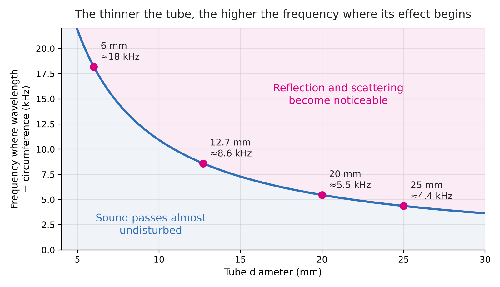
So at what frequency does the wavelength equal the circumference of the tube (ka = 1)? Taking the speed of sound as 343 m/s (air at 20 °C) gives the following.
| Tube diameter | Circumference | Frequency where wavelength = circumference |
|---|---|---|
| 25 mm | approx. 79 mm | approx. 4.4 kHz |
| 20 mm | approx. 63 mm | approx. 5.5 kHz |
| 12.7 mm (1/2 inch) | approx. 40 mm | approx. 8.6 kHz |
| 6 mm | approx. 19 mm | approx. 18 kHz |
Formula: frequency = speed of sound ÷ circumference (circumference = 3.14 × diameter)
With a 20 mm tube, the effect begins to appear from several kilohertz upward. With a 6 mm rod, that boundary moves up close to the top of the audible range. This is why supports made for measurement are thin.
At the same thickness, round beats square
As long as the tube is thin compared with the wavelength, it makes almost no difference to the sound whether the section is round or square. The difference appears at high frequencies, where the wavelength approaches the thickness.
A square tube has flat faces. High-frequency sound reflects off a flat face the way light reflects off a mirror, so if a face points toward the microphone, the reflection returns as a concentrated bundle. Turning the face slightly changes how much comes back.
A cylinder has no flat face. Sound that strikes it spreads over a wide range of angles and does not return strongly in any one direction. Rotating the tube about its axis does not change its shape either, so the result is less likely to change each time the stand is set up again.
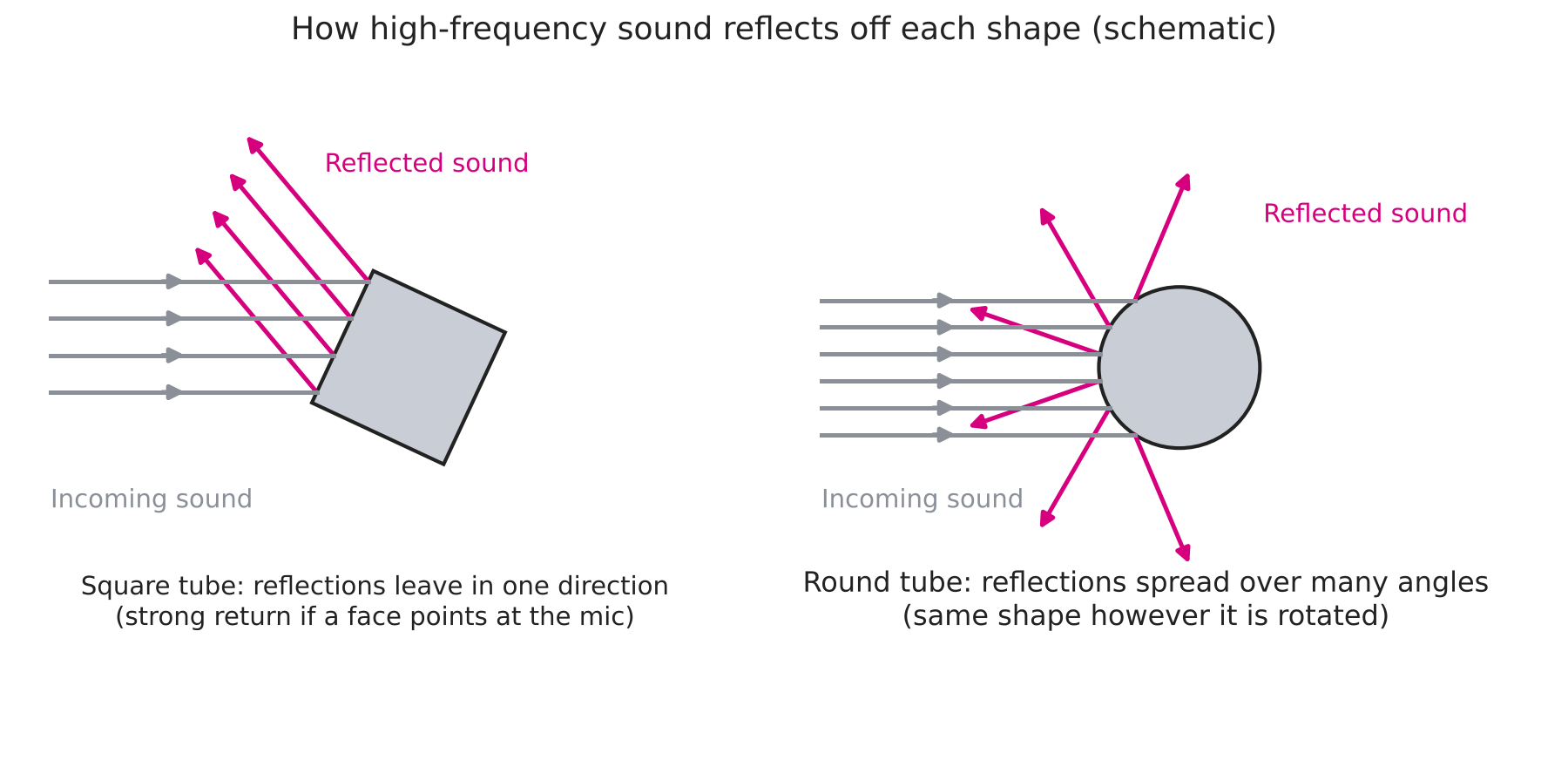
In measurement, an error that stays the same every time matters as much as an error that is small. Round tubing is a convenient shape for this kind of repeatability.
How microphones are supported in an anechoic room
An anechoic room removes reflections from the walls, ceiling and floor so that only the sound coming directly from the source is measured. Even with the room’s reflections gone, a stand right next to the microphone still reflects. In the tests used to qualify an anechoic room, keeping the microphone traversing equipment from disturbing the free field is itself a practical difficulty [5].
For this reason, precision measurements use the following techniques.
| Make it thin | Use the thinnest rods and tubes that will do the job. |
| Keep it away | Move thick uprights and clamps as far from the microphone as possible. |
| Put it behind | Mount the microphone end-on at the tip of a thin rod, so that the support is hidden behind the microphone as seen from the source. |
| Absorb it | Wrap sound-absorbing material around any fitting that has to stay close. |
Arc frames that place microphones on a hemisphere
These techniques are easiest to see in sound power level measurement. In a hemi-anechoic room, many microphones are placed on a hemispherical surface surrounding the source [9]. Every microphone brings a support into the room, and a forest of separate stands would mean worrying about reflections between the supports as well.
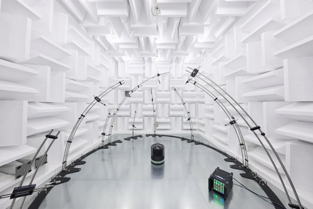
The solution is a frame of thin round tubing bent into arcs, as in the photo at the top of this article. Arches rising from a rail on the floor form the skeleton of the hemisphere, and each microphone is mounted at its set position on an arch.
The photo shows everything discussed so far.
| The tubing is thin | For the size of the room, the frame is strikingly slender. |
| There are no flat faces | Every arch is round tubing, with no plane facing a microphone. |
| The microphones stand off from the frame | Each one is carried on a thin arm toward the inside of the hemisphere instead of being fixed directly to the tube. |
| Round tubing can be bent | Bending a clean arc is far easier with round tube than with square. Here again the reasons for the round shape are both mechanical and acoustic. |
Where round tubing is a disadvantage
So far the round shape has had only advantages. There is one situation where it does not: wind.
When wind blows across a cylinder, vortices form alternately on either side behind it (a Kármán vortex street). These vortices produce a whistling sound. It is the same phenomenon that makes overhead wires sing in the wind, and it is called an Aeolian tone [6].
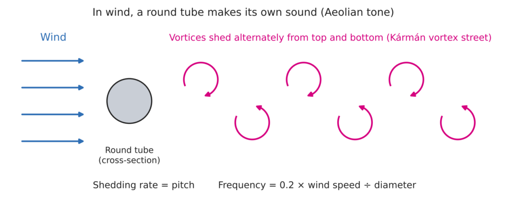
The pitch can be estimated with the following formula [6][7].
Frequency = 0.2 × wind speed ÷ diameter
The value 0.2 is the Strouhal number, which is about 0.2 for a circular cylinder over the usual range of wind speeds [7].
| Diameter | Wind speed 5 m/s | Wind speed 10 m/s |
|---|---|---|
| 20 mm | approx. 50 Hz | approx. 100 Hz |
| 6 mm | approx. 170 Hz | approx. 330 Hz |
In a wind tunnel or outdoors, a round stand or strut can become a noise source in its own right. Countermeasures that have been studied include streamlining the section and winding a thin wire around the cylinder in a spiral. One study reports that a section with a semicircular upstream side and a square downstream side lowered the Aeolian tone by about 10 dB compared with a plain cylinder [7].
Round is the better shape in a quiet room and the worse one in wind. No shape is right everywhere, and the answer depends on where the stand is used.
Does it matter for recording?
For music recording, there is almost no need to think about the round tube of the stand. Its effect is less than 1 dB in the treble, and moving the microphone a little or changing its angle makes a much larger difference.
What deserves attention is larger flat surfaces. The music stand is the obvious example. A study that measured the reflection from a music stand at a trumpet player’s position found that when the stand faced the receiver, the sound level at high frequencies rose by up to 9 dB [8]. A music stand holding a lyric sheet during a vocal take, a desk top in a home studio and a monitor screen all act in the same way.
Nearby flat surfaces come before thin round tubes. When you want to cut reflections in a recording, checking them in that order is the quickest route.
Summary
- Microphone stands use round tubing mainly for mechanical reasons: telescoping, clamping, strength and cost.
- In measurement, reflections from the stand can cause errors of around 0.5 dB at high frequencies.
- The frequency where the effect begins depends on the diameter: about 5.5 kHz for 20 mm and about 18 kHz for 6 mm.
- At the same thickness, a round section has no flat face, so its reflections spread out and vary less with orientation.
- Where wind reaches it, round tubing generates sound of its own through vortex shedding.
An anechoic room is a room without reflections, but the room alone does not decide the quality of a measurement. A true free field also depends on how the microphone is supported and on what else is brought into the room.
Sonora Technology designs anechoic rooms and anechoic boxes, and is glad to advise on measurement fixtures for use inside them.
Sources
- 1. John Atkinson, “Measuring Loudspeakers, Part Three”, Stereophile. https://www.stereophile.com/node/8300
- 2. “Linear microphone array for acoustic impulse response measurements using reciprocal method: Effects of microphone holder”, Acoustical Science and Technology, 42(6), Technical Report. https://www.jstage.jst.go.jp/article/ast/42/6/42_E2119/_article
- 3. P. M. Morse and K. U. Ingard, Theoretical Acoustics, Princeton University Press, 1968, Chapter 8 (scattering of a plane wave by a cylinder). See also the explanatory demo: https://dougjam.github.io/demos/sound-scattering-cylinder
- 4. “An approximate treatment of high-frequency scattering”, Mathematical Proceedings of the Cambridge Philosophical Society (the scattering coefficient of a cylinder approaches 2 in the high-frequency limit). https://resolve.cambridge.org/core/journals/mathematical-proceedings-of-the-cambridge-philosophical-society/article/an-approximate-treatment-of-highfrequency-scattering/6171D4147D504654C105B28675EF669E
- 5. Peutz, paper presented at Internoise 2001 (qualification of anechoic rooms to ISO 3745 and the measuring set-up). https://www.peutz.nl/sites/peutz.nl/files/publicaties/Peutz_Publicatie_ML_Internoise_08-2001.pdf
- 6. MONOist, article on analysing Kármán vortices (explains the Aeolian tone and the Strouhal number; in Japanese). https://monoist.itmedia.co.jp/mn/spv/1601/12/news027_3.html
- 7. KAKENHI project 09450084, research results (Aeolian tone of circular cylinders, Strouhal number, reduction methods; in Japanese). https://kaken.nii.ac.jp/ja/grant/KAKENHI-PROJECT-09450084
- 8. Paper in the AES E-Library (acoustic effect of a music stand at the musician’s position). https://aes2.org/publications/elibrary-page/?id=18622
- 9. ISO 3745, Acoustics: Determination of sound power levels of noise sources using sound pressure, precision methods for anechoic and hemi-anechoic rooms. Specifies the hemispherical measurement surface and the arrays of microphone positions for hemi-anechoic rooms. Table of contents: https://www.din.de/de/mitwirken/normenausschuesse/nals/veroeffentlichungen/wdc-beuth:din21:147792977/toc-1901033/download