
Measurable Range in Anechoic and Hemi-Anechoic Chambers
10/13/2026
MFAC / MSAC
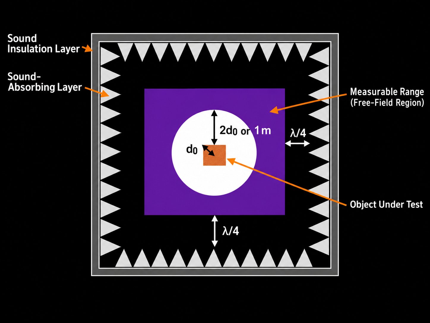
The measurable range of an anechoic or hemi-anechoic chamber is the region in which the intended free-field acoustic measurement conditions can be achieved. The diagram below illustrates this range in plan view. The purple area indicates the measurable region (free-field region), excluding the area too close to the sound source.
How Is the Measurable Range Determined?
1. Distance from the Sound-Absorbing Layer
The measurement region is set back from the sound-absorbing layer (acoustic wedges) by approximately one-quarter of the wavelength (λ/4) at the frequency of interest. For example, at 150 Hz, this distance is approximately 560 mm under the assumptions used in the original Japanese article. The required distance varies with frequency and the assumed speed of sound.
2. Distance from the Sound Source
The circular region around the reference center of the sound source is excluded from the illustrated measurable range. Its indicated radius is 2d₀ or 1 m, depending on the applicable measurement condition. The symbol d₀ denotes the characteristic source dimension, which is defined differently for an anechoic chamber and a hemi-anechoic chamber.
Characteristic Source Dimension (d₀)
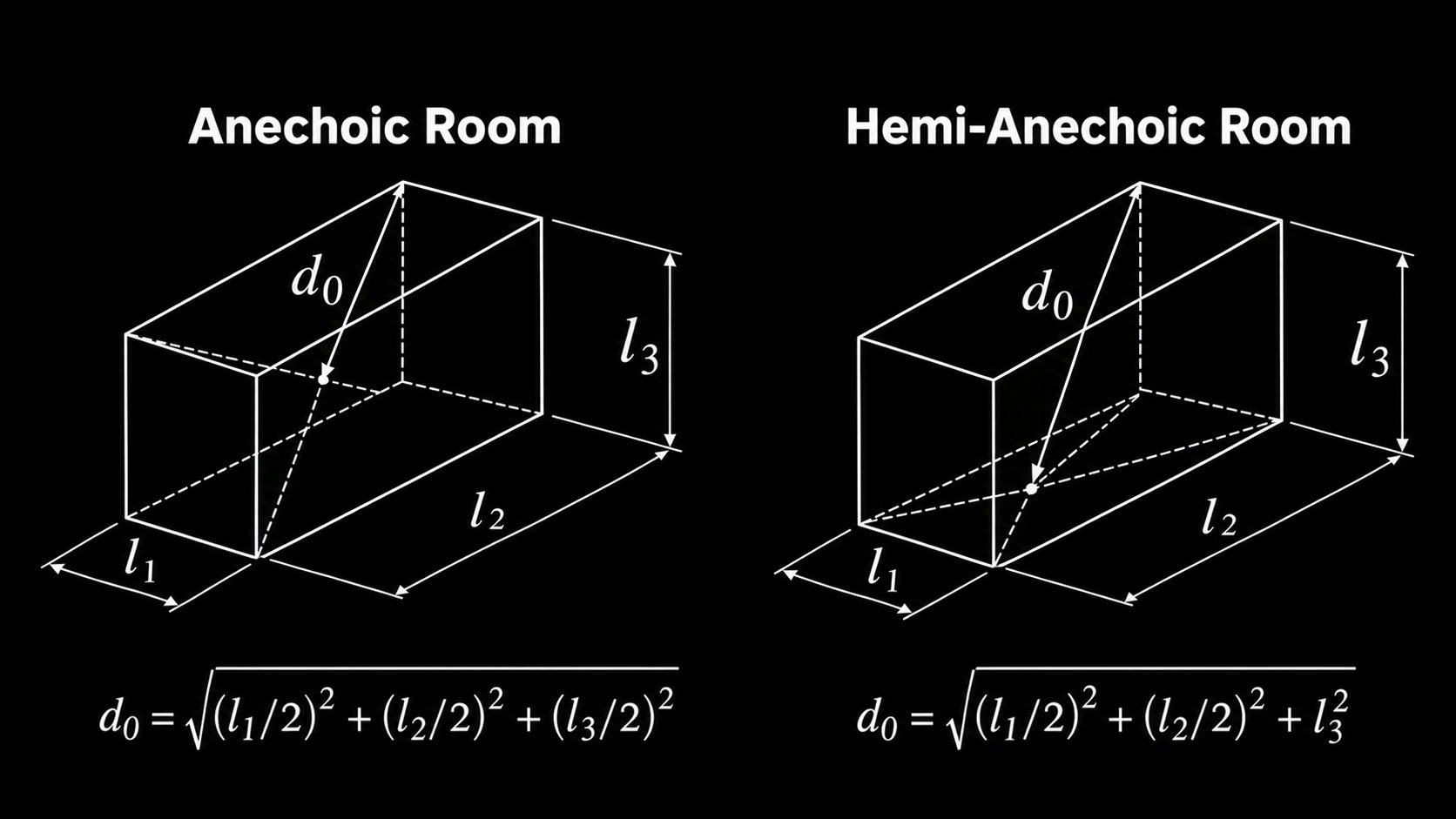
The reference box is the smallest rectangular box enclosing the sound source as illustrated below. The calculation of d₀ depends on whether the chamber is fully anechoic or hemi-anechoic.
Fully Anechoic Chamber
The reference center is at the geometric center of the box. The characteristic dimension d₀ is the distance from that center to the farthest corner:
d₀ = √[(l₁/2)² + (l₂/2)² + (l₃/2)²]
Hemi-Anechoic Chamber
The reference center is located at the center of the box on the reflecting floor plane. The characteristic dimension d₀ is the distance from this center to the farthest upper corner:
d₀ = √[(l₁/2)² + (l₂/2)² + l₃²]
Reference Standard: ISO 3745:2012
ISO 3745:2012(E), Figure 1, illustrates the reference boxes, measurement-surface centers and characteristic source dimensions for anechoic and hemi-anechoic rooms. The original Japanese article notes that the standard uses the characteristic source dimension d₀ rather than the earlier 2a-based expression. These geometrical distinctions are important when selecting measurement positions and defining the usable measurement region.
Reference: ISO 3745:2012(E), Figure 1 — Reference box, centre for the measurement surface (when using the geometric centre of the source) and characteristic source dimensions for application in an anechoic and a hemi-anechoic room.
For detailed chamber design, measurement planning, or applicable conformity requirements, consult the complete relevant edition of ISO 3745.