New Technology for Anechoic Chamber silencers?
07/08/2024

Others
Have you seen a muffler attached to the exhaust of a motorcycle before ?
There’s a significant size difference between having it attached and not having it attached.
The magical sound suppression effect comes from the structure of the muffler. Adding sound-absorbing materials to the muffler can also enhance its sound suppression capabilities. However, in this article, we will focus on the sound suppression mechanism inherent in the muffler’s structure and aim to clarify it.
We plan to leverage this principle to enhance the silencers in our company’s anechoic chambers.
First, let me state the conclusion.
The volume of sound is determined by fluctuations in atmospheric pressure (also referred to as static pressure). The structure of the muffler reduces this static pressure, thereby lowering the sound level.
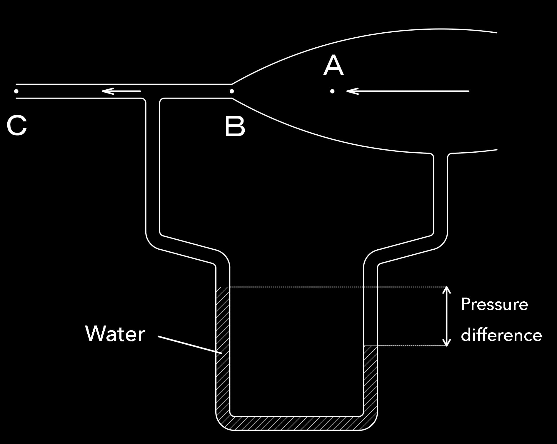
Please take a look at this diagram.

This is a Venturi tube, which demonstrates Bernoulli’s principle. In a nutshell, Bernoulli’s principle states that a fluid’s total energy, comprising dynamic pressure (determined by the fluid’s speed) and static pressure (derived from atmospheric pressure), remains constant along the streamline.
Let’s first consider point A, where air flows into this wide tube.
At point A, the total pressure received is : Total Pressure at A = Dynamic Pressure + Static Pressure = 1/2V2+P/ρ
Here, V represents the fluid velocity, P is the static pressure, and ρ denotes the fluid density.
Now, looking at point B, according to the conservation of total pressure, to deliver a constant volume of air, the space narrows, requiring the air to flow faster to be delivered, thus increasing its speed.
At the exit point C, the velocity increases to its maximum. Therefore, at point C, the dynamic pressure is maximized, while the static pressure is minimized.
To demonstrate this, we set up a U-shaped tube below and fill it with water.
At point D, due to the increase in dynamic pressure, the static pressure decreases. This causes the static pressure in the tube to push upwards to balance it out, creating an upward pressure.
As a result, the water in the left side of the tube rises. The difference in water column height represents the difference in static pressure.
And the sound coming out from point C becomes quieter due to the decrease in static pressure.
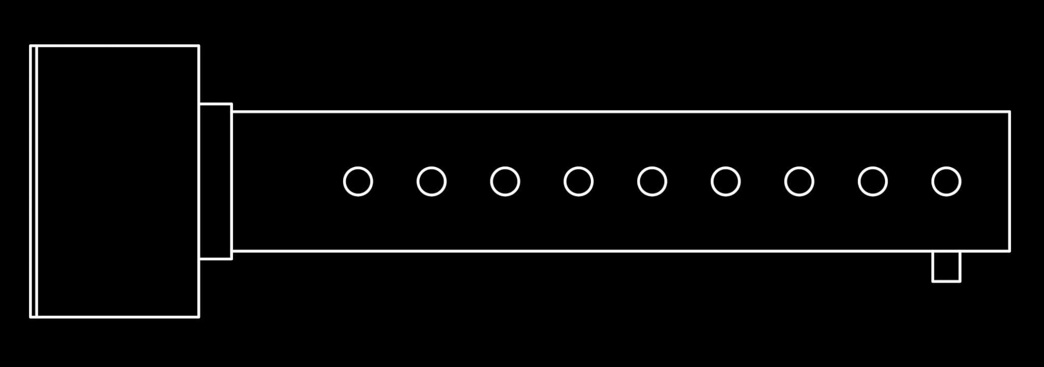
By the way, this is how a typical muffler structure looks like.

The long narrow section functions similarly to the left side of a Venturi tube.
To aid in understanding, let us provide two more examples.
When riding a train, you often hear the announcement to “please stand behind the yellow line.”
The reason for this is that the air flowing over the surface of the train entering the station platform at high speed results in high dynamic pressure and low static pressure.
Due to the low static pressure, there is a force extending towards the train from the surroundings. This force can cause people to lean towards the train, which is very dangerous as they might fall onto the tracks.
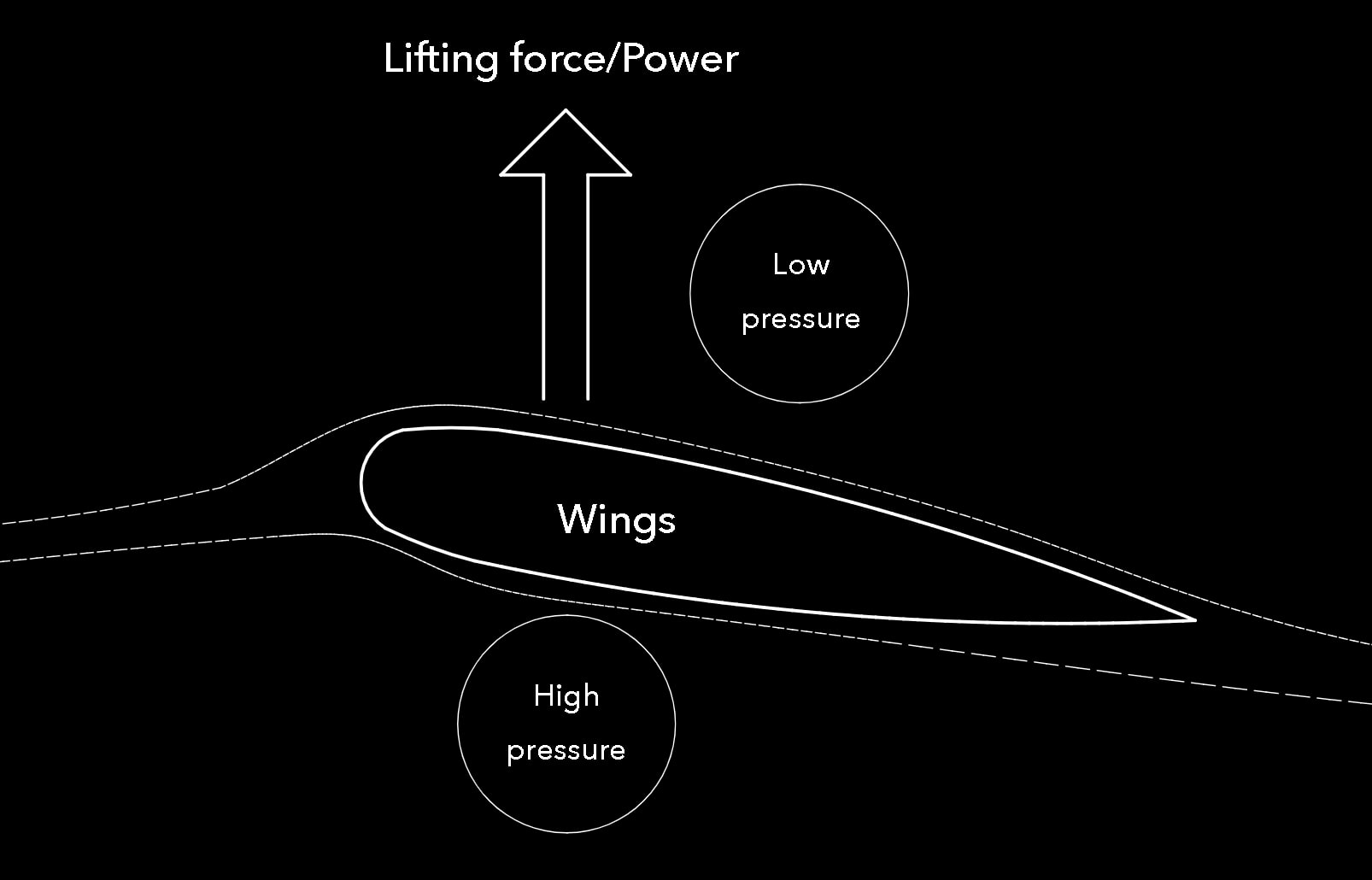
Another example is an airplane wing. Let’s take a look at this diagram.

I’ll skip the detailed principles, but due to the shape of this wing, the static pressure on the upper surface decreases while it remains relatively strong on the lower surface, creating a pressure difference.
As a result, upward lift is generated.
Have you understood the principle of the baffle structure now?
Summary
We anticipate that this baffle structure will greatly benefit the silencers in our anechoic chambers. Therefore, we plan to incorporate it into future silencer development efforts, aiming to create even higher-performance silencers.